Skip to content
(425) 740-3700
/
(888) 333-0299
Gallery
Resource
Careers
Contact
Gallery
Resource
Careers
Contact
Gallery
Resource
Careers
Contact
Gallery
Resource
Careers
Contact
A
B
C
D
E
F
G
H
J
K
M
N
P
Q
R
S
T
U
V
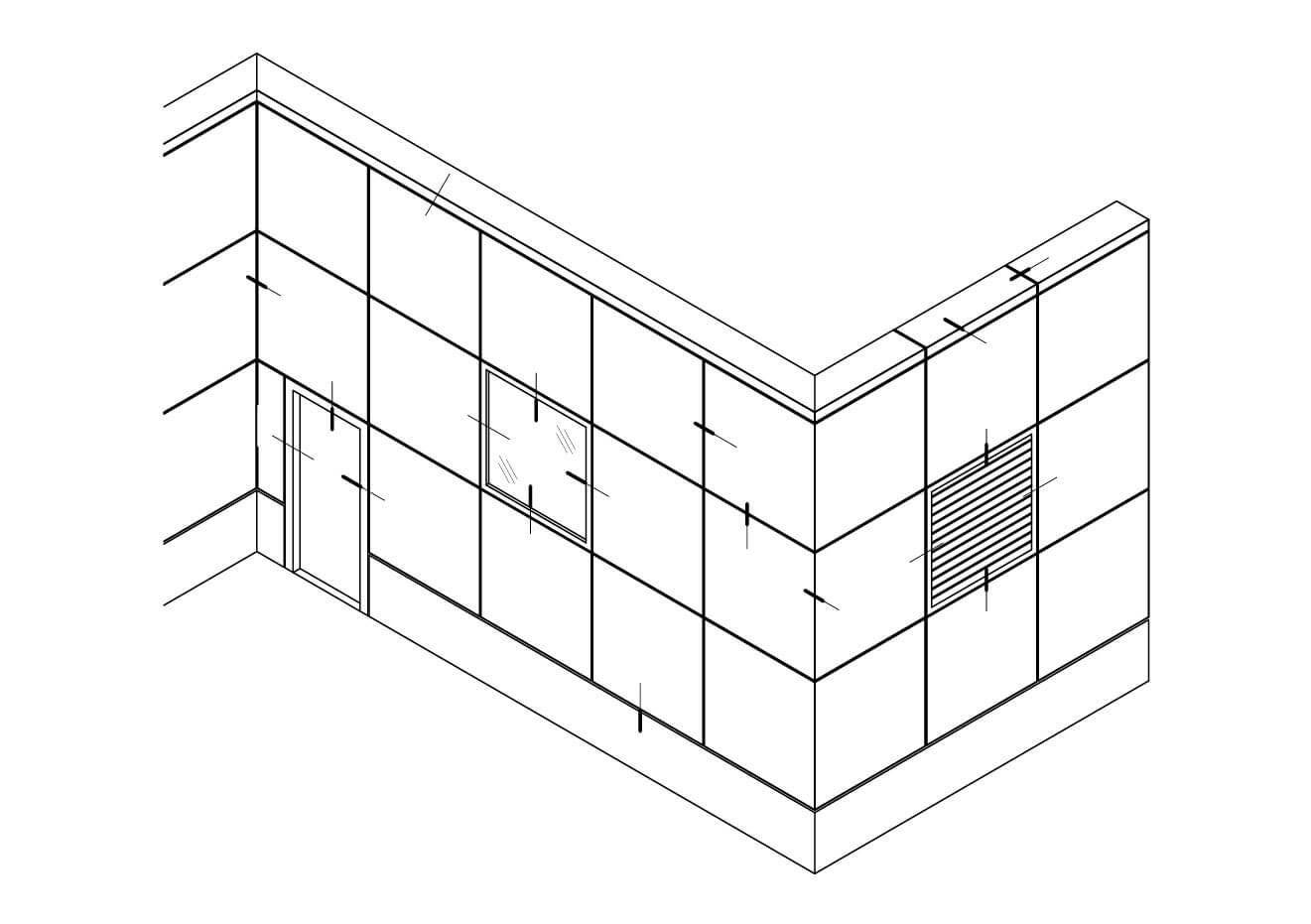
EXTRUSION MOUNTED PLATE RETURN DETAILS
Back Routed Wet
Vertical Stacking
Product Details
Inboard Insulation
Outboard Insulation
Product Brochure
Installation Guide
Specifications
AL-VS Spec .050
AL-VS Spec .063
AL-VS Spec .080
Testing Data
AAMA PDF
ASTM PDF
Color Chart
LEED® Credit
Dual Interlocking
Product Details
Inboard Insulation
Outboard Insulation
Product Brochure
Installation Guide
Specifications
AL-DI Spec .050
AL-DI Spec .063
AL-DI Spec .080
Testing Data
AAMA PDF
Color Chart
LEED® Credit
Extrusion Mounted Plate Return
Product Details
ALPR Back Routed Dry Joint
ALPR Back Routed Wet Joint
ALPR Welded Wet Joint
ALPR Welded Dry Joint
Product Brochure
Installation Guide
Specification Guide
Testing Data
AAMA PDF
ASTM PDF
Color Chart
LEED® Credit
Extrusion Mounted Plate Floating
Product Details
Standards Inboard
Standards Outboard
Product Brochure
Testing Data
NC AL PF AAMA 508 Std-r1
Specifications
AL Hook and Pin System
AL-HP Details
Product Brochure
Specifications (Coming Soon)
Aluminum Panel Gallery
Dual Interlocking & Vertical Stacking Gallery
Plate Floating & Plate Return Gallery
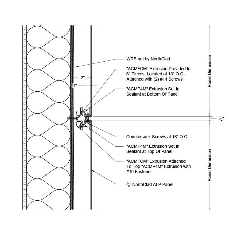
A - Section - TYPICAL ALP HORIZONTAL PANEL JOINT
Section detail showing AL panel mounting at typical ALP horizontal panel joint for Back Routed Wet Extrusion Mounted Plate Return.
PDF
DWG
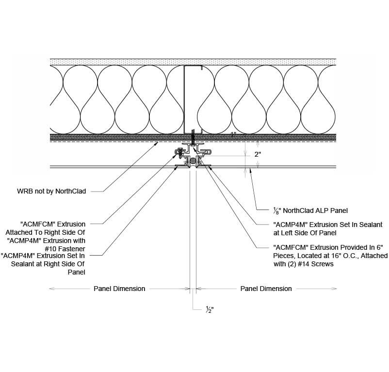
B - Plan - TYPICAL ALP VERTICAL PANEL JOINT
Plan section detail showing AL panel mounting at typical ALP vertical panel joint for Back Routed Wet Extrusion Mounted Plate Return.
PDF
DWG
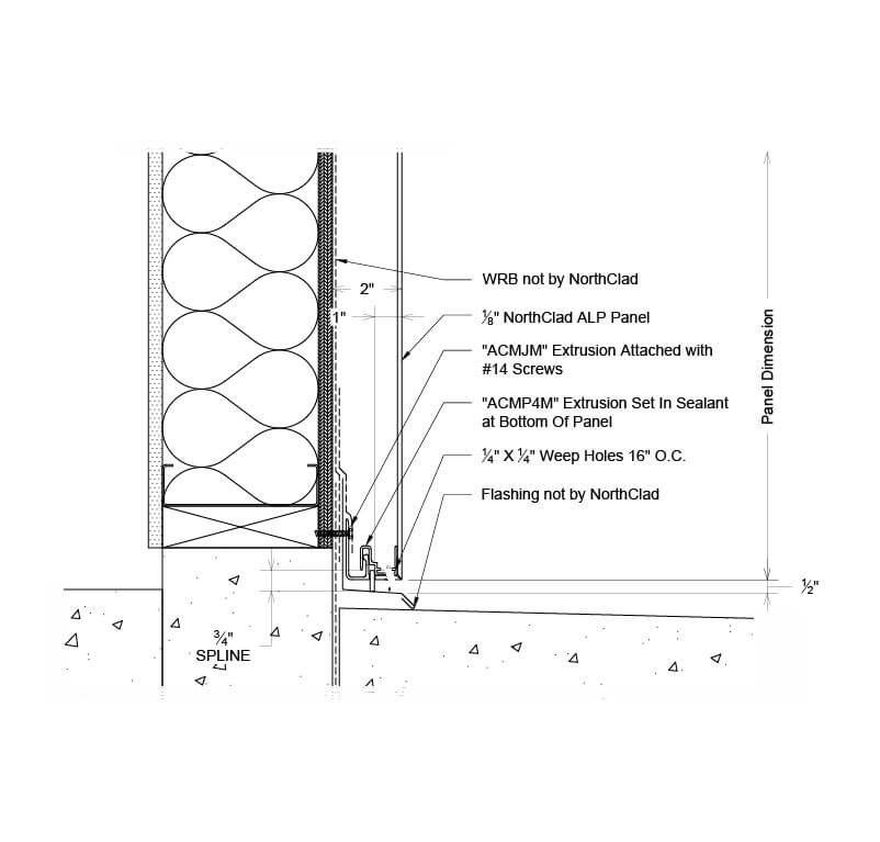
C - Section - ALP BASE OF PANEL WALL
Section detail showing AL panel mounting at ALP base of panel wall for Back Routed Wet Extrusion Mounted Plate Return.
PDF
DWG
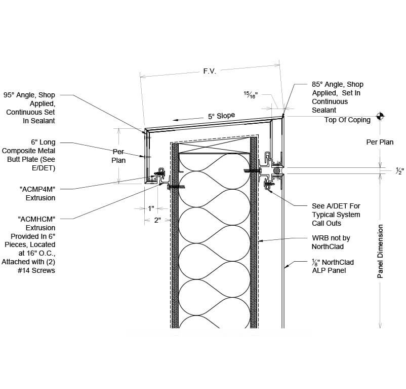
D - Section - ALP PANEL COPING
Section detail showing AL panel mounting at ALP panel coping for Back Routed Wet Extrusion Mounted Plate Return.
PDF
DWG
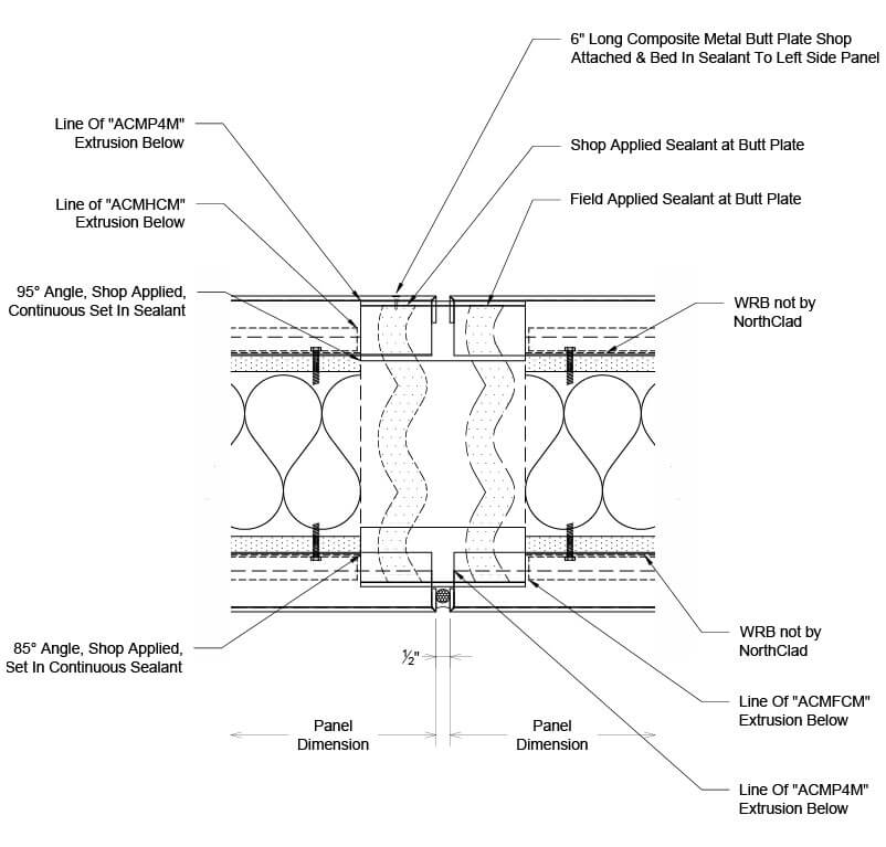
E - PLAN - ALP PANEL COPING SPLICE
Plan section detail showing AL panel mounting at ALP panel coping splice for Back Routed Wet Extrusion Mounted Plate Return.
PDF
DWG
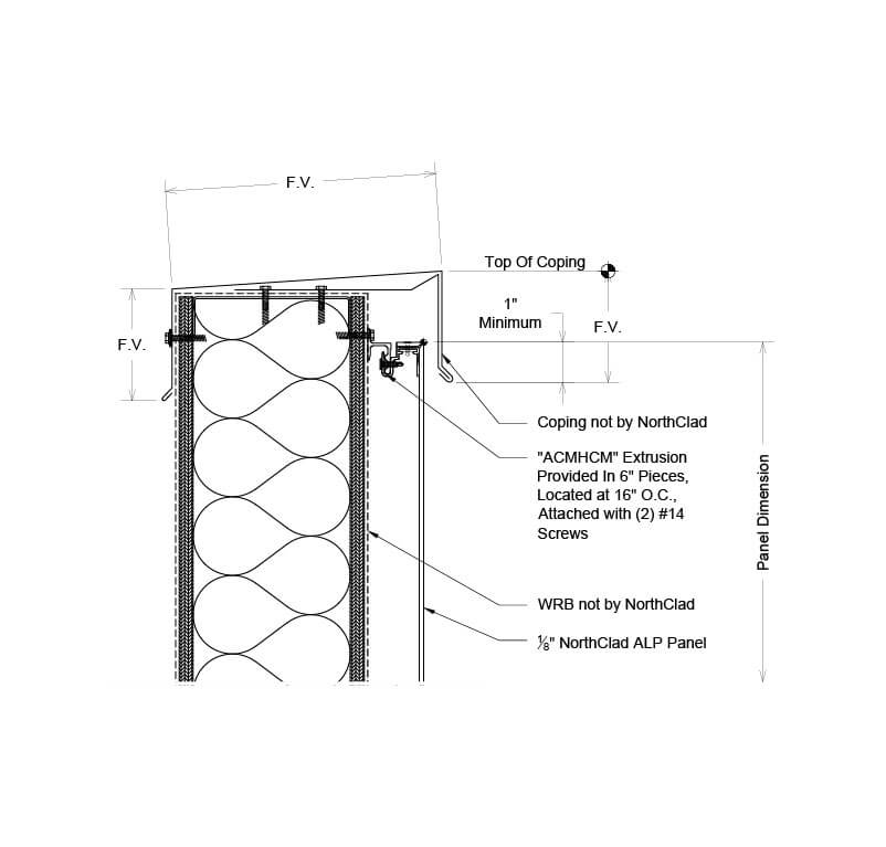
F - SECTION - ALP PANEL AT LIGHT GAUGE FORMED COPING
Section detail showing AL panel mounting at ALP panel at light gauge formed coping for Back Routed Wet Extrusion Mounted Plate Return.
PDF
DWG
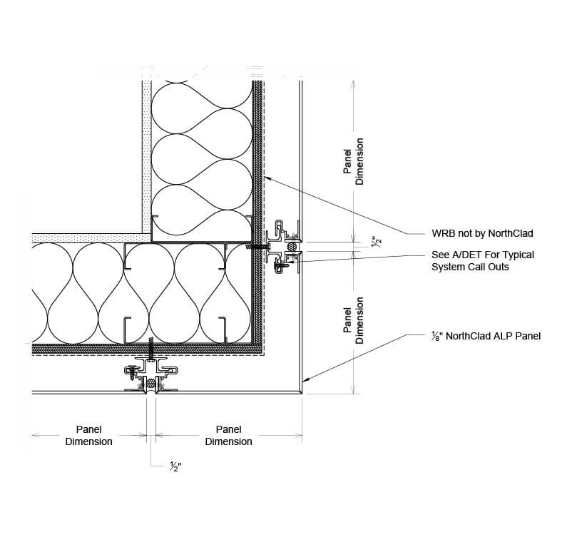
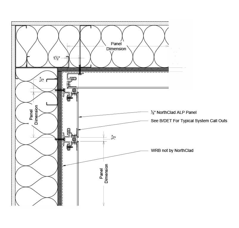
G - Plan - ALP Outside Corner
Plan section detail showing AL panel mounting at ALP outside corner for Back Routed Wet Extrusion Mounted Plate Return.
PDF
DWG
H - Plan - ALP Inside Corner
Section detail showing AL panel mounting at ALP inside corner for Back Routed Wet Extrusion Mounted Plate Return.
PDF
DWG
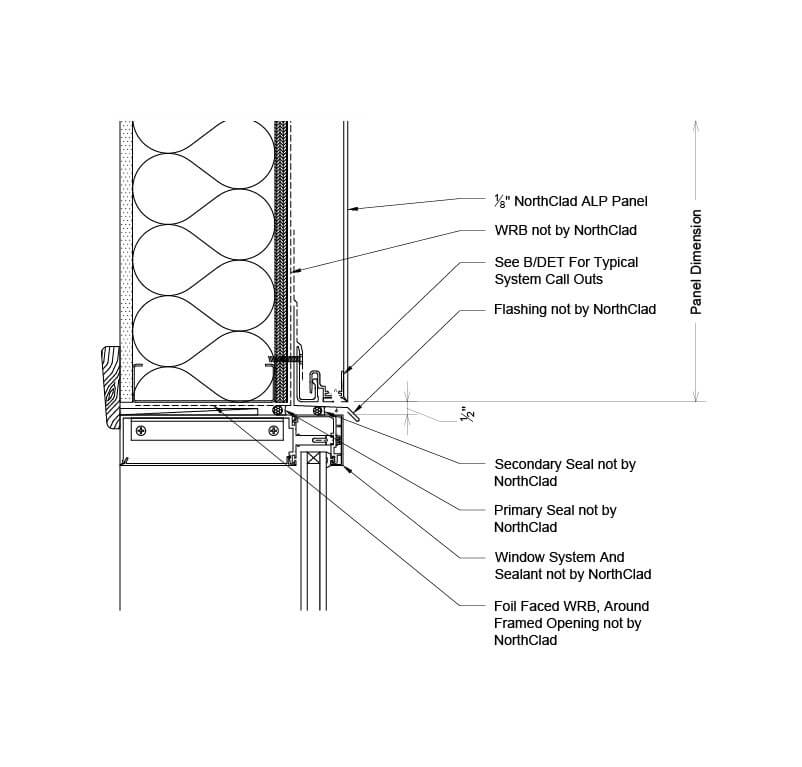
J - Section - ALP Panel at Window/CW Head
Section detail showing AL panel mounting at ALP panel at window/cw head for Back Routed Wet Extrusion Mounted Plate Return.
PDF
DWG
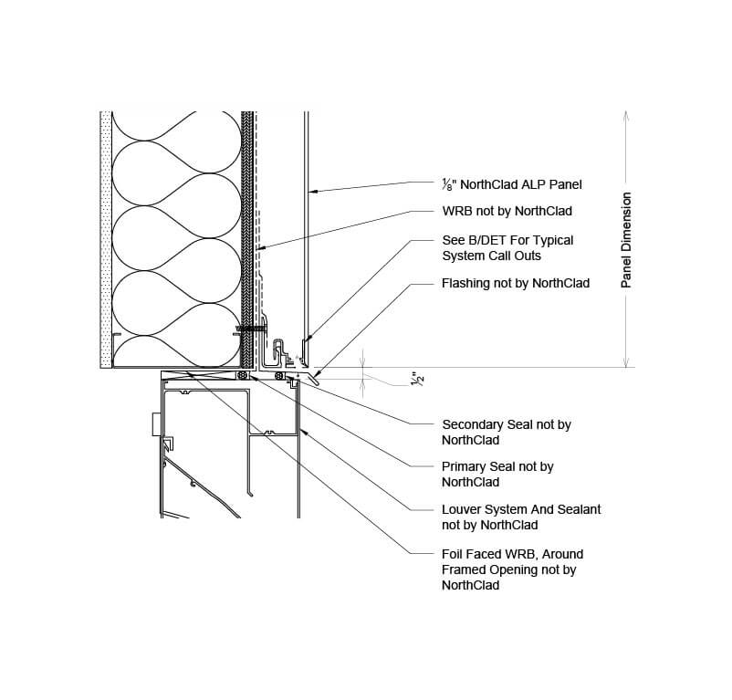
K - Section - ALP Panel at Louver Head
Section detail showing AL panel mounting at ALP panel at Louver head for Back Routed Wet Extrusion Mounted Plate Return.
PDF
DWG
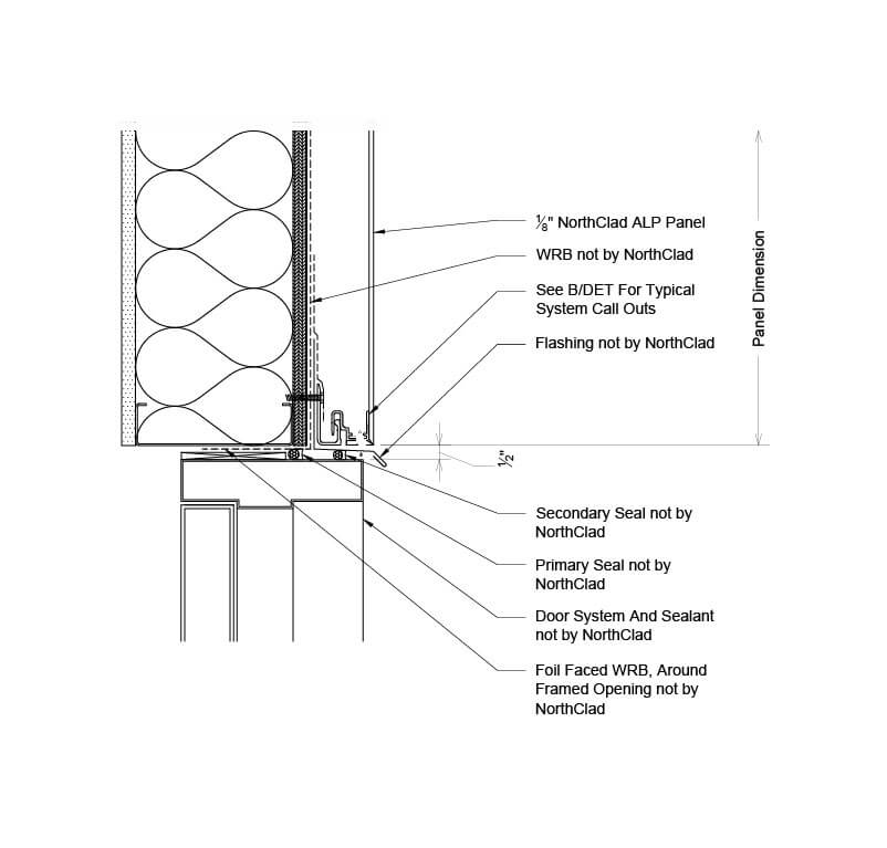
M - Section - ALP Panel at Hollow Metal Door Head
Section detail showing AL panel mounting at ALP panel at hollow metal door head for Back Routed Wet Extrusion Mounted Plate Return.
PDF
DWG
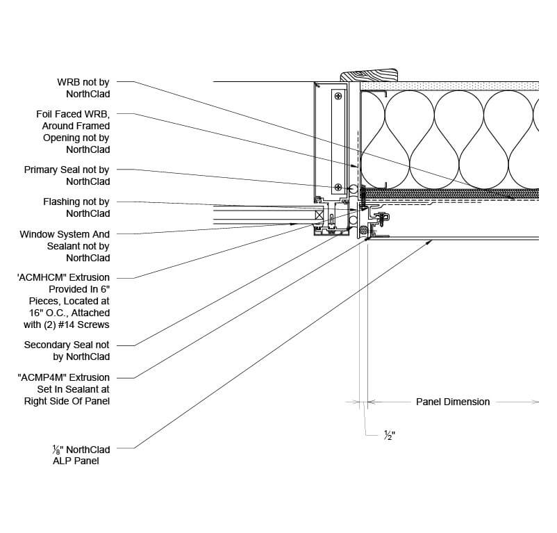
N - Plan - ALP Panel at Left Side Window/CW Jamb
Plan section detail showing AL panel mounting at ALP panel at left side window/cw jamb for Back Routed Wet Extrusion Mounted Plate Return.
PDF
DWG
P - Plan - ALP Panel at Left Side Louver Jamb
Plan section detail showing AL panel mounting at ALP panel at left side Louver jamb for Back Routed Wet Extrusion Mounted Plate Return.
PDF
DWG
Q - Plan - ALP Panel at Left Side Hollow Metal Door Jamb
Plan section detail showing AL panel mounting at ALP panel at left side hollow metal door jamb for Back Routed Wet Extrusion Mounted Plate Return.
PDF
DWG
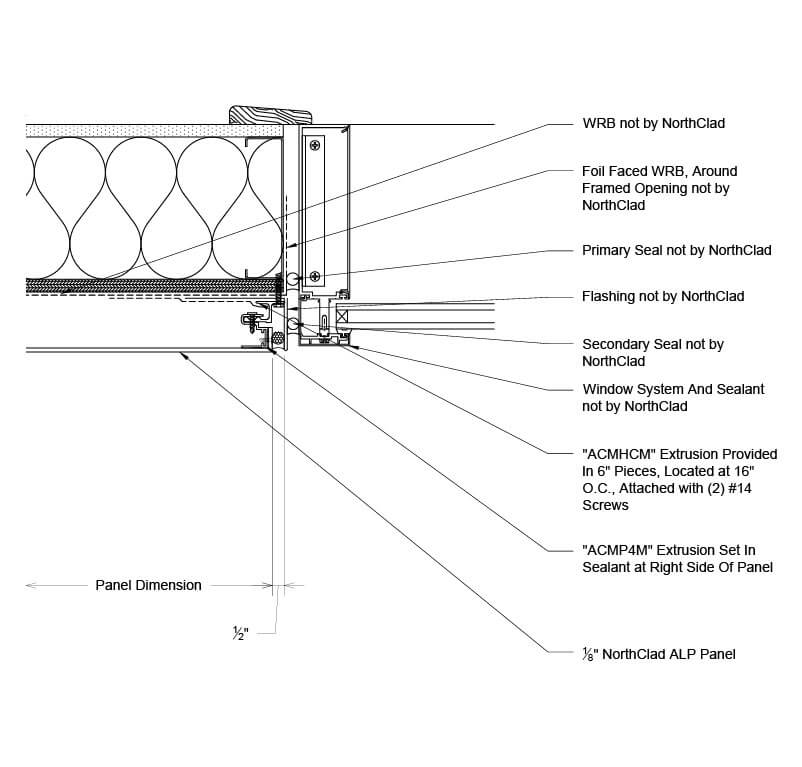
R - Plan - ALP Panel at Right Side Window/CW Jamb
Plan section detail showing AL panel mounting at ALP panel at right side window/cw jamb for Back Routed Wet Extrusion Mounted Plate Return.
PDF
DWG
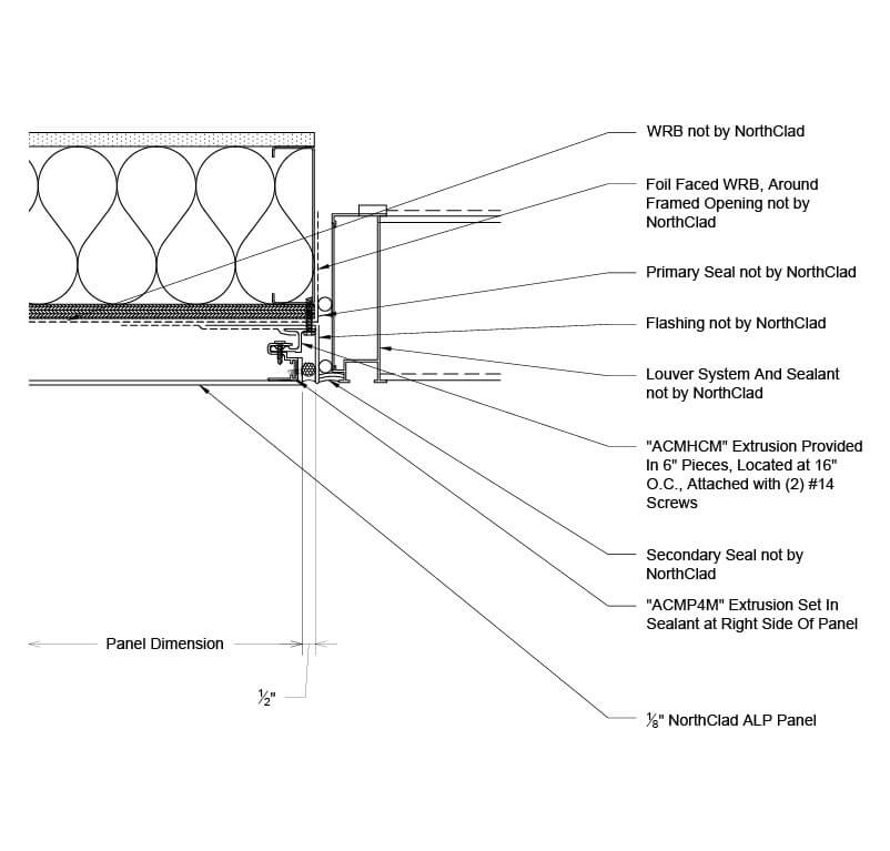
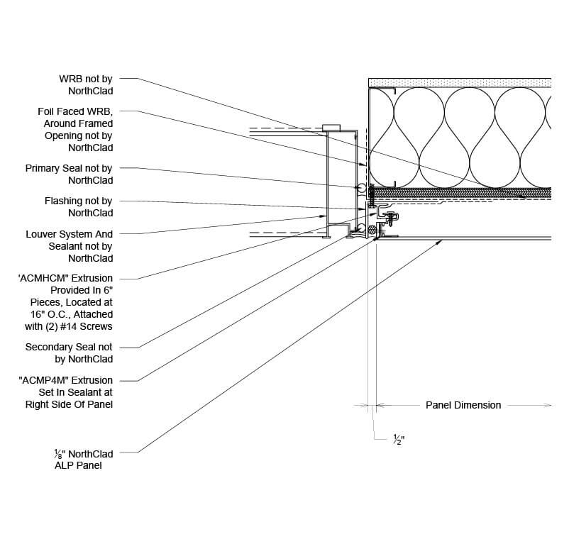
S - Plan - ALP Panel at Right Side Louver Jamb
Plan section detail showing AL panel mounting at ALP panel at right side Louver jamb for Back Routed Wet Extrusion Mounted Plate Return.
PDF
DWG
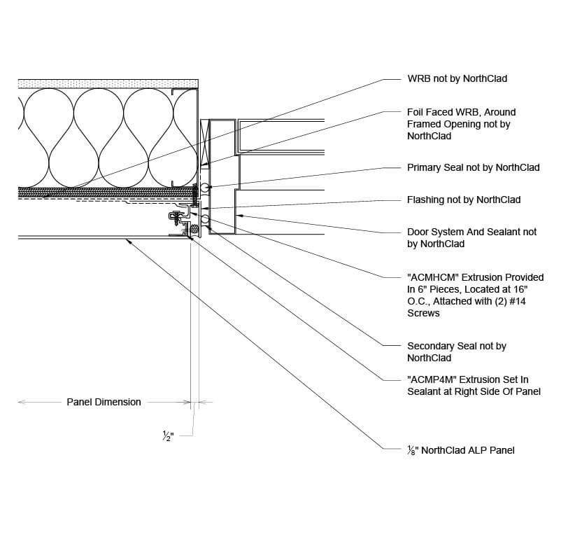
T - Plan - ALP Panel at Right Side Hollow Metal Door Jamb
Plan section detail showing AL panel mounting at ALP panel at right side hollow metal door jamb for Back Routed Wet Extrusion Mounted Plate Return.
PDF
DWG
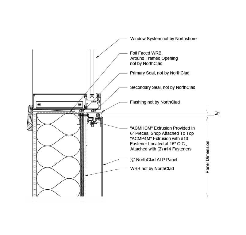
U - Section - ALP Panel at Window/CW Sill
Section detail showing AL panel mounting at ALP panel at window/cw sill for Back Routed Wet Extrusion Mounted Plate Return.
PDF
DWG
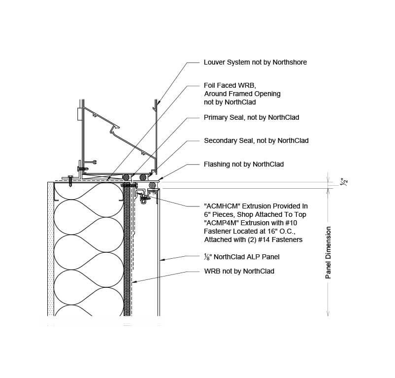
V - Section - ALP Panel at Louver Sill
Section detail showing AL panel mounting at ALP panel at Louver sill for Back Routed Wet Extrusion Mounted Plate Return.
PDF
DWG
Scroll to Top