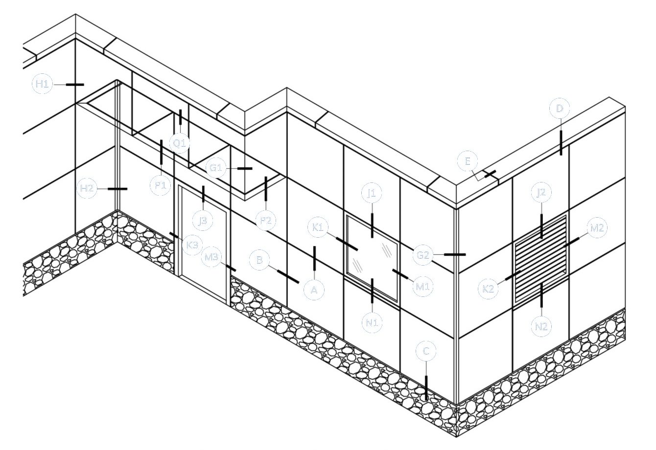
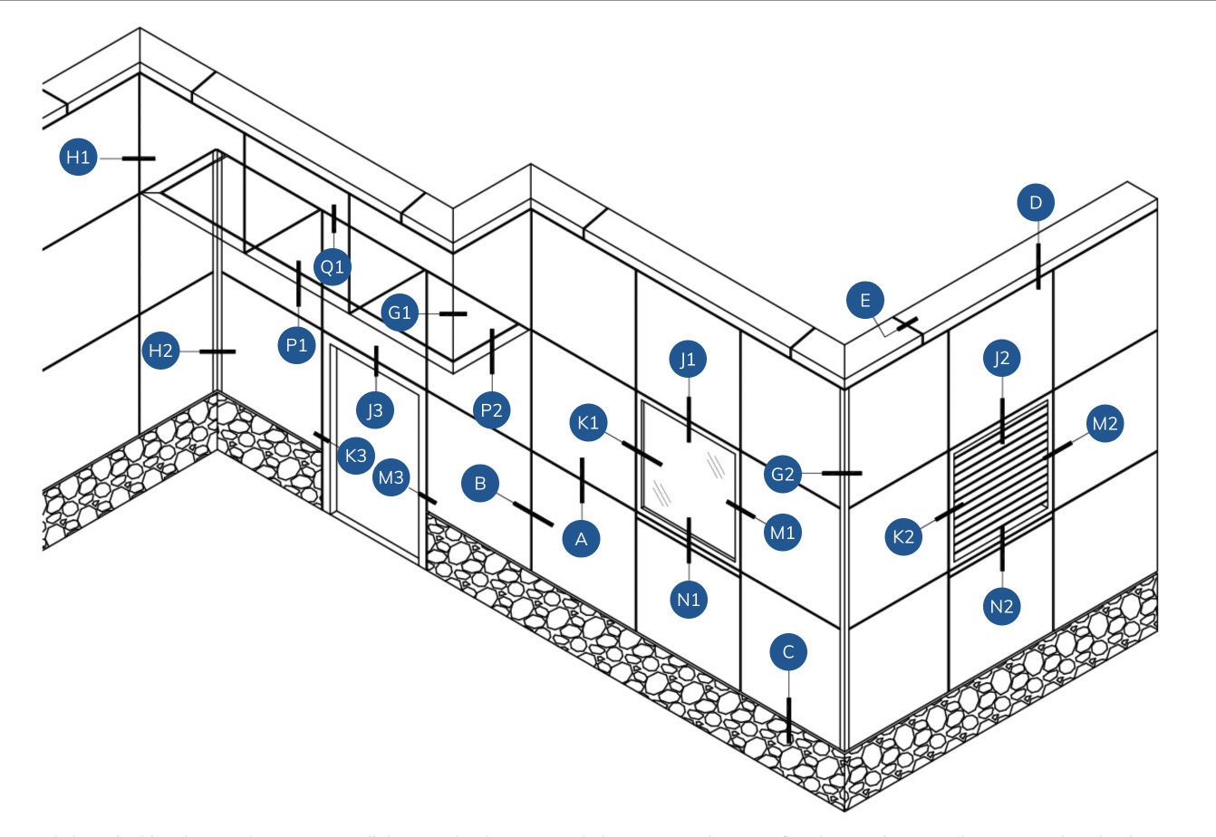
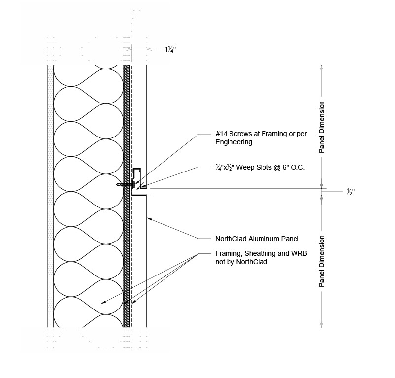
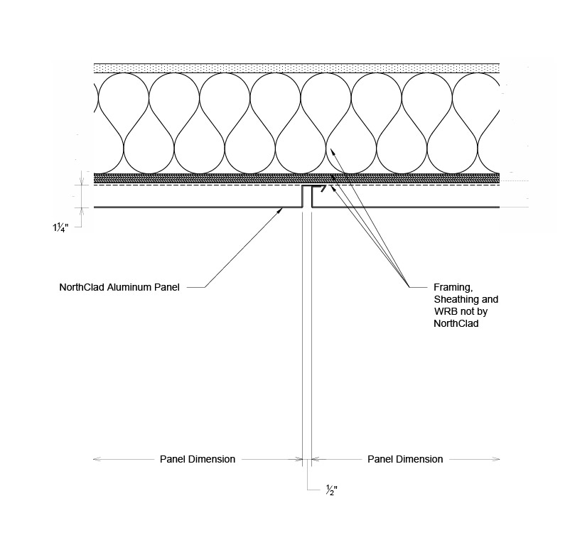
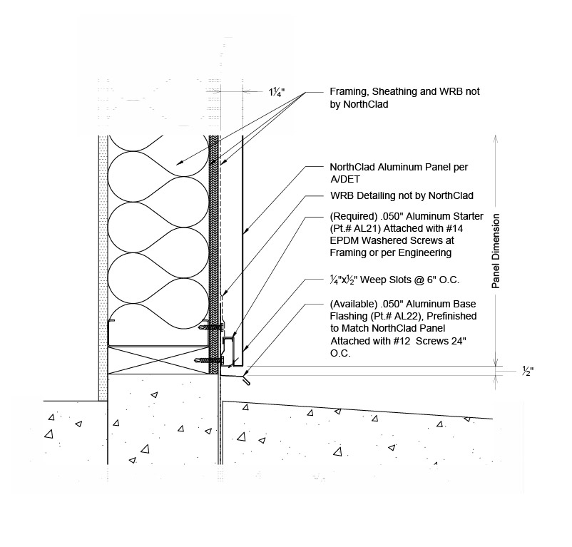
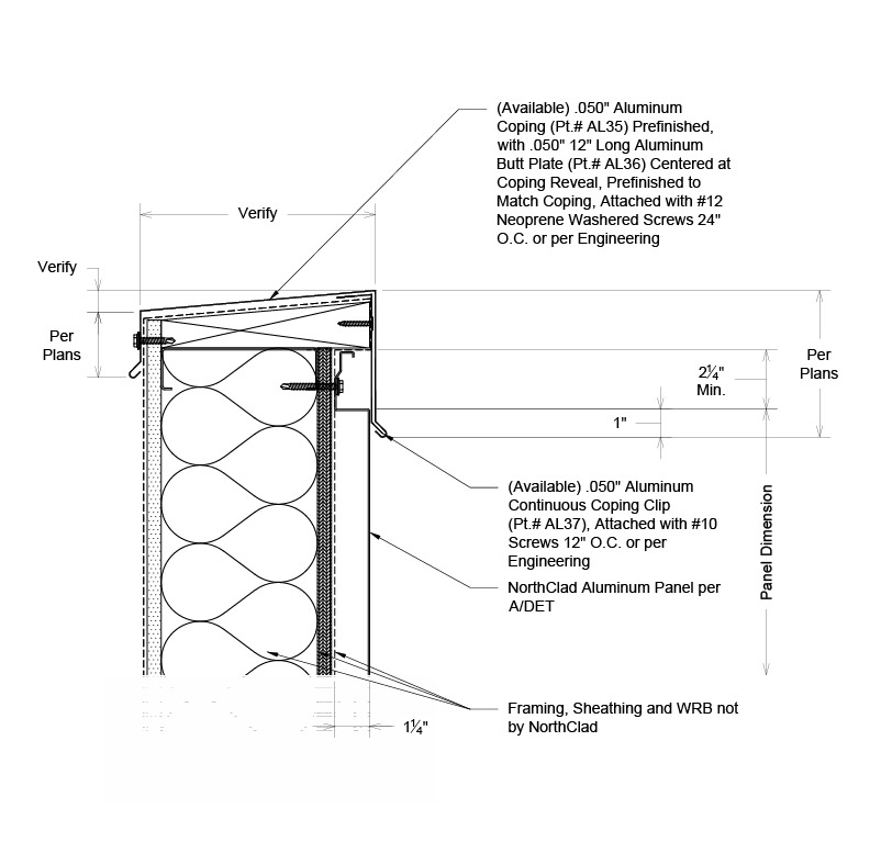
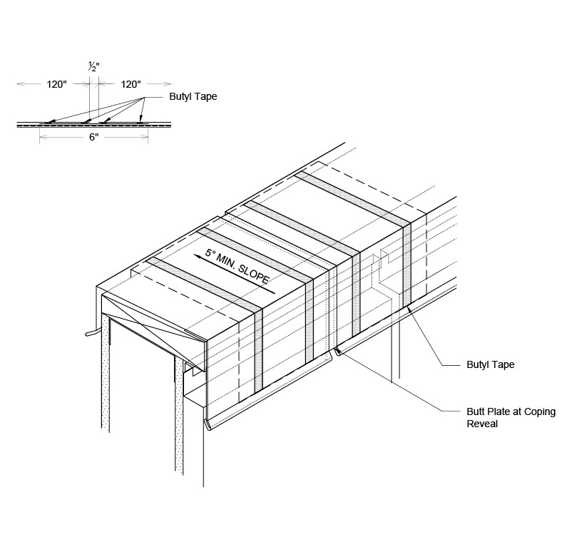
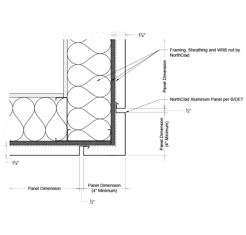
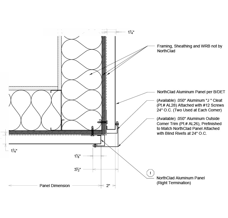
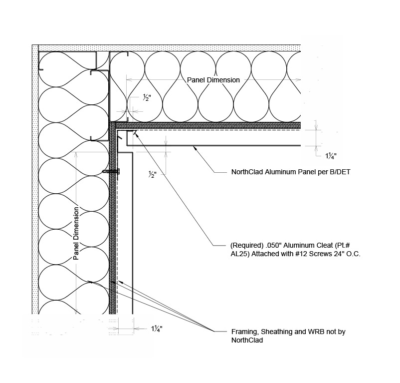
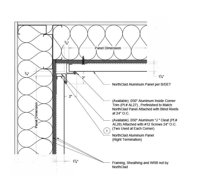
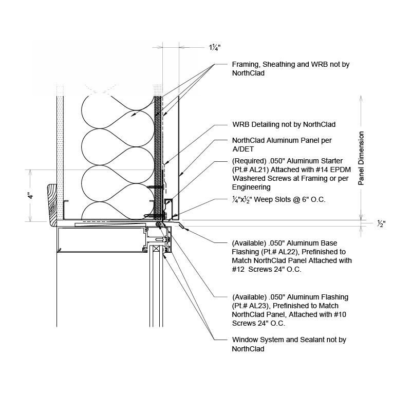
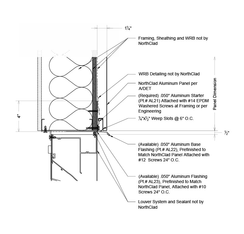
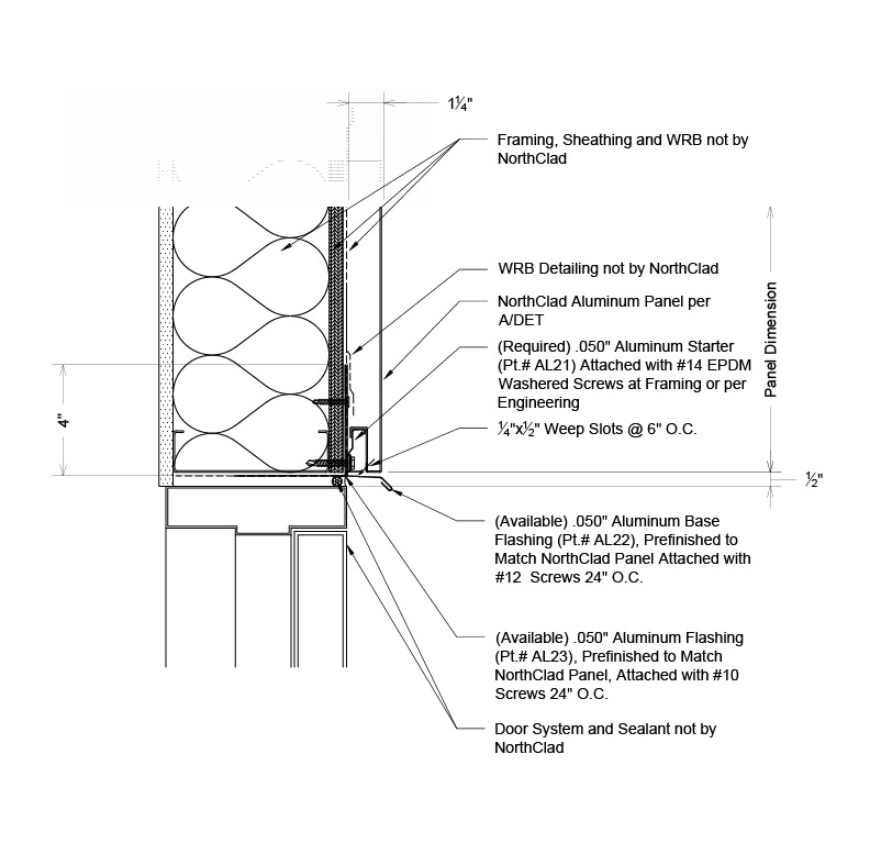
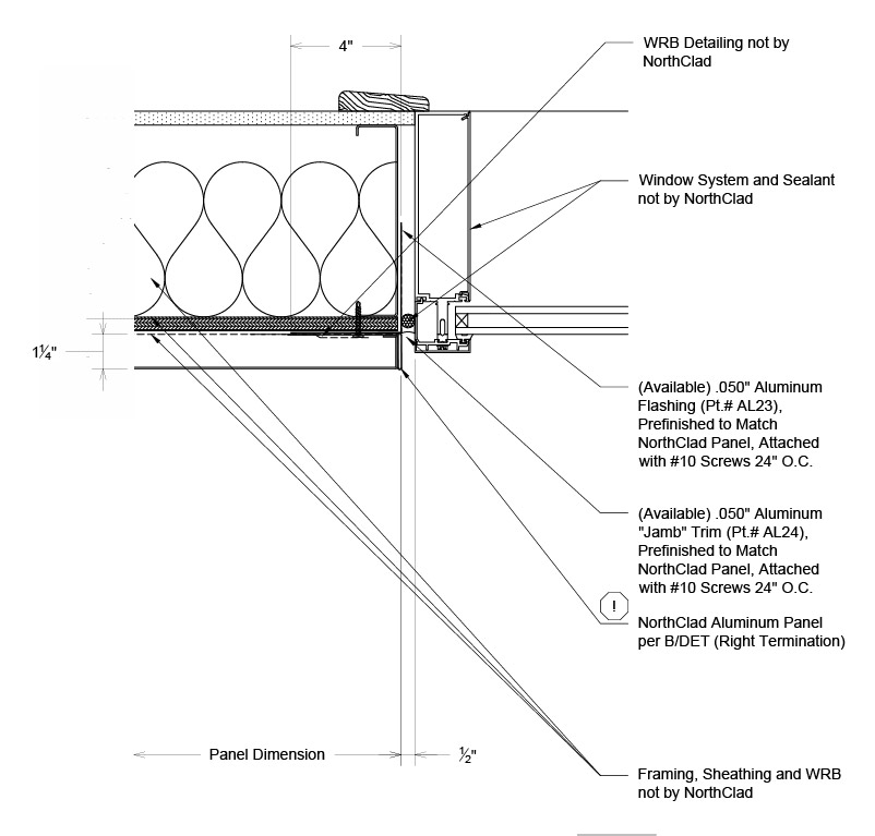
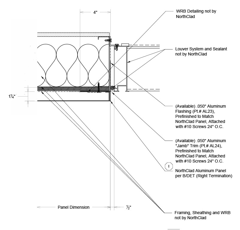
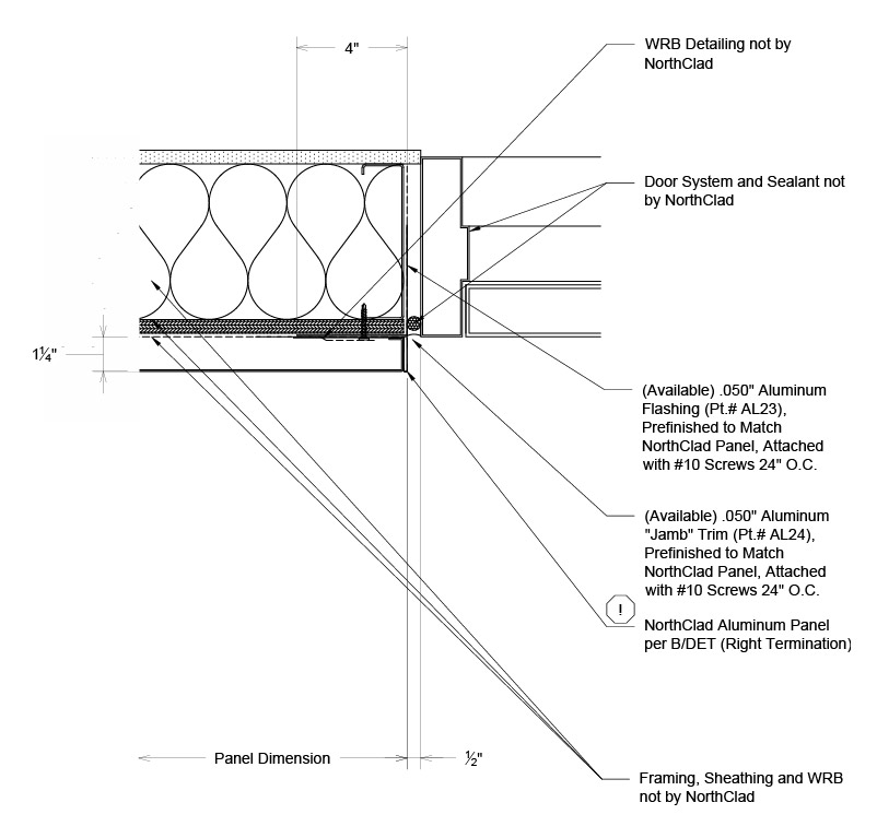
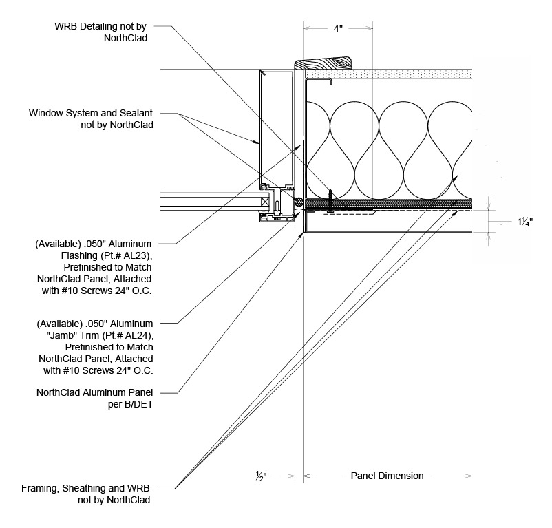
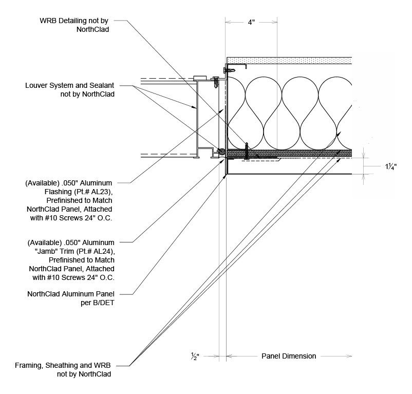
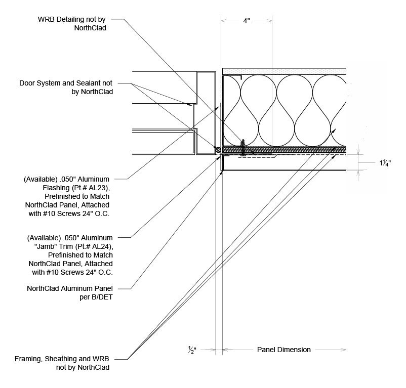
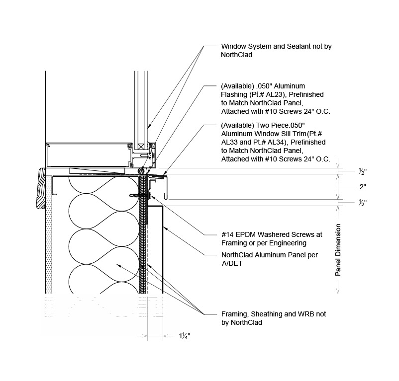
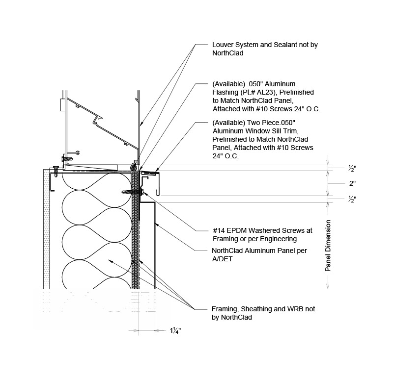
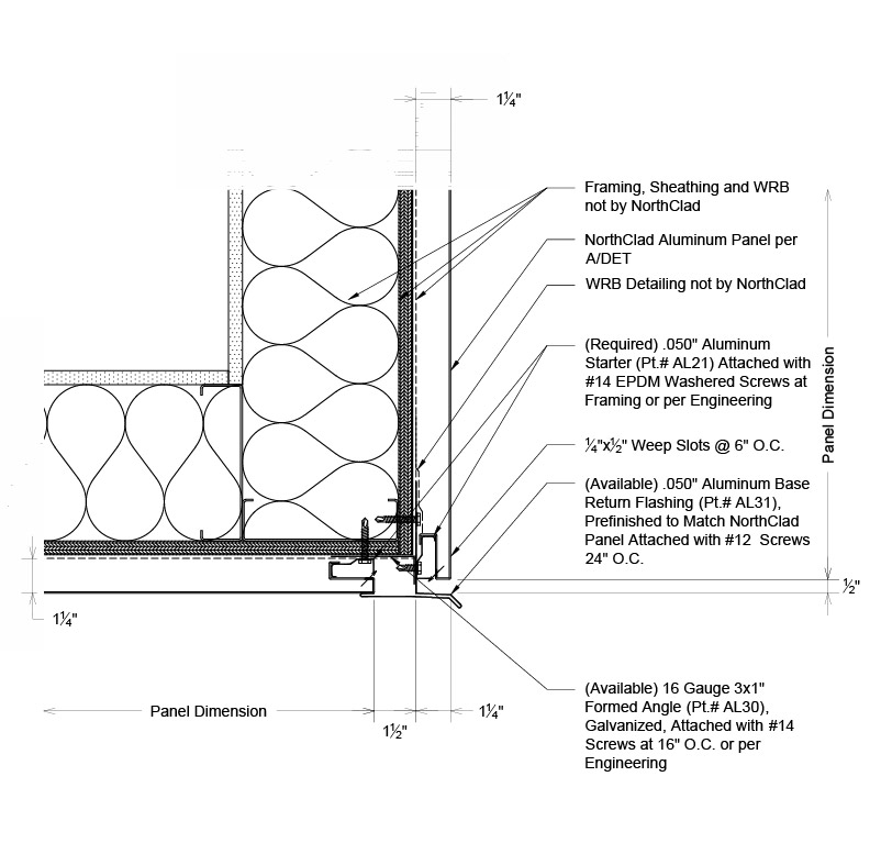
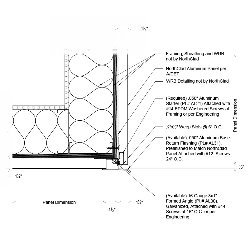
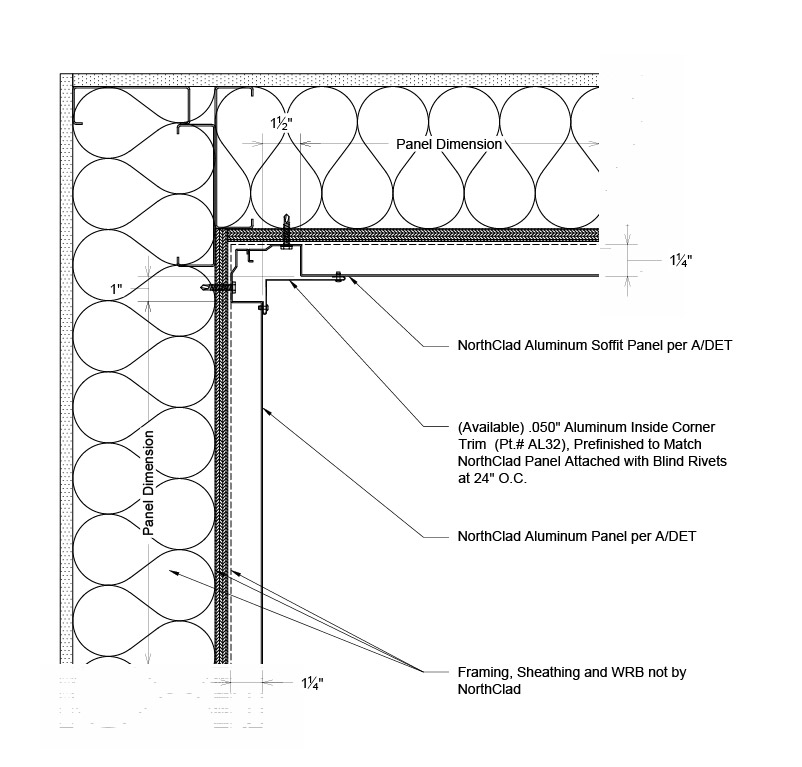
DUAL INTERLOCKING DETAILS Inboard Insulation Vertical Stacking Product Details Inboard Insulation Outboard Insulation Product Brochure Installation Guide Specifications AL-VS Spec .050 AL-VS Spec .063 AL-VS Spec .080 Testing Data AAMA PDF ASTM PDF Color Chart LEED® Credit Dual Interlocking Product Details Inboard Insulation Outboard Insulation Product Brochure Installation Guide Specifications AL-DI Spec .050 AL-DI Spec .063 AL-DI Spec .080 Testing Data AAMA PDF Color Chart LEED® Credit Extrusion Mounted Plate Return Product Details ALPR Back Routed Dry Joint ALPR Back Routed Wet Joint ALPR Welded Wet Joint ALPR Welded Dry Joint Product Brochure Installation Guide Specification Guide Testing Data AAMA PDF ASTM PDF Color Chart LEED® Credit Extrusion Mounted Plate Floating Product Details Standards Inboard Standards Outboard Product Brochure Testing Data NC AL PF AAMA 508 Std-r1 Specifications AL Hook and Pin System AL-HP Details Product Brochure Specifications (Coming Soon) Aluminum Panel Gallery Dual Interlocking & Vertical Stacking Gallery Plate Floating & Plate Return Gallery Vertical Stacking Product Details Inboard Insulation Outboard Insulation Product Brochure Installation Guide Specifications AL-VS Spec .050 AL-VS Spec .063 AL-VS Spec .080 Testing Data AAMA PDF ASTM PDF Color Chart LEED® Credit Dual Interlocking Product Details Inboard Insulation Outboard Insulation Product Brochure Installation Guide Specifications AL-DI Spec .050 AL-DI Spec .063 AL-DI Spec .080 Testing Data AAMA PDF Color Chart LEED® Credit Extrusion Mounted Plate Return Product Details ALPR Back Routed Dry Joint ALPR Back Routed Wet Joint ALPR Welded Wet Joint ALPR Welded Dry Joint Product Brochure Installation Guide Specification Guide Testing Data AAMA PDF ASTM PDF Color Chart LEED® Credit Extrusion Mounted Plate Floating Product Details Standards Inboard Standards Outboard Product Brochure Testing Data NC AL PF AAMA 508 Std-r1 Specifications AL Hook and Pin System AL-HP Details Product Brochure Specifications (Coming Soon) Aluminum Panel Gallery Dual Interlocking & Vertical Stacking Gallery Plate Floating & Plate Return Gallery H1 H2 P1 Q1 G1 J3 K3 M3 B P2 K1 A N1 J1 G2 M1 C K2 N2 J2 M2 D E Click on the blue dots on the map to scroll down to the descriptions below to get a close up of each area shown on the map. Or, download the entire package details right here: FULL PACKAGE DETAILS - PDF FULL PACKAGE DETAILS - DWG A - Section - Horizontal Joint Section cut showing panel AL panel mounting at horizontal joint locations for AL Dual Interlocking with Inboard Insulation. PDF DWG B - Plan - Vertical Joint Plan section showing AL Dual Interlocking panel mounting at vertical joint condition for AL Dual Interlocking with Inboard Insulation. PDF DWG C - Section - Base Of Wall Section cut showing AL panel mounting at base of wall condition for AL Dual Interlocking with Inboard Insulation. PDF DWG D - Section - Coping Section detail showing AL Dual Interlocking panel condition at top of wall for AL Dual Interlocking with Inboard Insulation. PDF DWG E - Isometric - Coping Splice Isometric detail showing coping section splicing method for AL Dual Interlocking with Inboard Insulation. PDF DWG G1 - Plan - Outside Corner Without Trim Plan section at outside corner condition with panels wrapping corner for AL Dual Interlocking with Inboard Insulation. PDF DWG G2 - Plan - Outside Corner With Trim Plan section at outside corner condition with trim flashing for AL Dual Interlocking with Inboard Insulation. PDF DWG H1 - Plan - Inside Corner Without Trim Plan section showing inside corner condition at AL Dual Interlocking panels without trim flashing for AL Dual Interlocking with Inboard Insulation. PDF DWG H2 - Plan - Inside Corner With Trim Plan section showing inside corner condition with trim flashing for AL Dual Interlocking with Inboard Insulation. PDF DWG J1 - Section - Window Head Section cut showing window head condition at AL Series Dual Interlocking panels for AL Dual Interlocking with Inboard Insulation. PDF DWG J2 - Section - Louver Head Section cut showing louver head flashing at AL Series for AL Dual Interlocking with Inboard Insulation. PDF DWG J3 - Section - Door Head Section cut showing door head flashing at AL Series Dual Interlocking panels for AL Dual Interlocking with Inboard Insulation. PDF DWG K1 - Plan - Window At Left Jamb Plan section showing left window jamb condition at panels for AL Dual Interlocking with Inboard Insulation. PDF DWG K2 - Plan - Louver At Left Jamb Plan section showing left louver jamb condition at panels for AL Dual Interlocking with Inboard Insulation. PDF DWG K3 - Plan - Door At Left Jamb Plan section showing panels at left door jamb condition for AL Dual Interlocking with Inboard Insulation. PDF DWG M1 - Plan - Window At Right Jamb Aluminum panel condition at right window jamb for AL Dual Interlocking with Inboard Insulation. PDF DWG M2 - Plan - Louver At Right Jamb Plan section showing right louver jamb at AL Series for AL Dual Interlocking with Inboard Insulation. PDF DWG M3 - Plan - Door At Right Jamb Plan section showing right door jamb at panels for AL Dual Interlocking with Inboard Insulation. PDF DWG N1 - Section - Window Sill Section cut showing window sill condition for AL Dual Interlocking with Inboard Insulation. PDF DWG N2 - Section - Louver Sill Section cut showing louver sill condition at AL Series for AL Dual Interlocking with Inboard Insulation. PDF DWG P1 - Section - Fascia To Soffit Section cut showing condition at soffit transition for AL Dual Interlocking with Inboard Insulation. PDF DWG P2 - Section - Fascia To Soffit Section cut showing condition at fascia transition to soffit for AL Dual Interlocking with Inboard Insulation. PDF DWG Q1 - Section - Soffit At Top Of Wall Section cut showing condition at soffit transition to wall for AL Dual Interlocking with Inboard Insulation. PDF DWG